Screw Parts
This description of screw parts is going to be a work in progress for
some time to come. Verbal descriptions of screw parts can only go
so far in conveying the parts. To try to more fully convey what
the parts are, examples have been drawn up to help with the
descriptions. The screw elements have been drawn in a very
general manner and are intended to convey the basics concepts of screw
geometry, not the geometry of any given extruder manufacturer.
The geometries are not quite correct, but are close enough to
convey the concepts to an audience wanting to learn about food
extrusion. The geometries used were for the purpose of ease of
drawing the parts.
The focus of this page is twin-screw extrusion. Single screw
extruders will have some parts and geometries not used or not possible
with
twin-screw extruders. This page will not show all of the parts
possible or available with twin-screw extrusion, but will focus on the
most common parts.
The basic use of measure on an extruder is the diameter of the screw
part. Using the diameter of the screw as the basic unit of
measure allows
extruder lengths and screw profiles to be described using a single set
of terms and measures from the smalllest extruder to the largest.
This can be best observed by looking at a screw element in
the axial direction (from the "front" or the "back" of the
screw). In many of the images below, there is a sphere 1D in
diameter to make visualization of the length of pieces in Diameters
more easy.
The length of screw parts are described in terms of diameters. In
general, the helical screw parts will be 0.5D, 1.0D, or 1.5D.
Other lengths are possible and available, depending on the
manufacturer.
The pitch of the screws are expressed in terms of the number of
diamters it takes for the flight to wrap 1 full revolution around the
screw (see images below). The most common pitches tend to be
0.25D, 0.5D, 0.75D, and 1.0D. The 0.25D pitch tends to be a
single-flight screw, this has not yet been drawn up for this site.
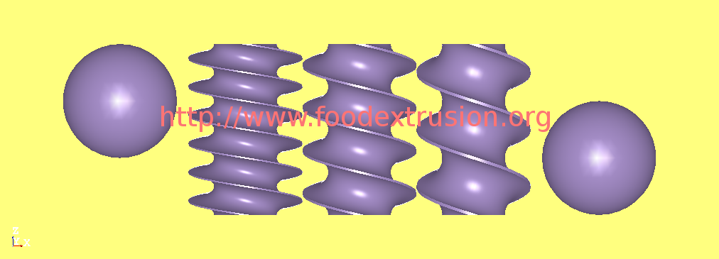
Below are images of the screw parts of different pitches. On the
left and right are the sphere 1D in diameter for comparison. The
spheres make it relatively easy to see these parts are 1.5D in
length. The screw element on the left has a pitch of 0.5, the
middle screw element has a pitch of 0.75, and the screw element on the
right has a pitch of 1.0. Using the screw element on the right
(1.0 pitch), you can follow the flight on the bottom of the image as it
rotates around the element (hiden behind the piece for part of the
revolution). When 1 full revolution around the element is
completed, the distance along the element is 1.0 D, so the point where
full rotation is completed is equal in height to the diameter of the
sphere (1.0 D). The 0.75 Pitch piece will complete a full
rotation of the flight in 0.75 D along the screw (or 2 rotations for
the 1.5 D length). The 0.5 Pitch will make 1 full rotation around
the screw in 0.5 D along the screw (or 3 rotations for the 1.5 D length.
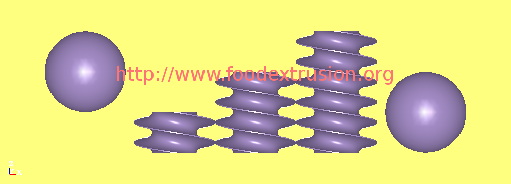
The length of these conveying pieces are typically 0.5 D, 1.0 D, and
1.5 D. The pieces for the three pitches are below (1.0 D pitch,
then 0.75 D pitch, then 0.5 D pitch).
Images for 1.0 D pitch (also call "full pitch")

Images for 3/4 pitch:

Images for 1/2 pitch:
Conveying elements put work into the extudate slowly, paddles
(shearlocks) put work into the profile more rapidly. A paddle is
essentially an oval piece that is a poor conveying element, even when
configured as part of a group of elements set to "forward
conveying". Forward conveying is essentially lining the paddles
up so the general direction of the progression of the longest dimension
of the paddles (lobe) continue the direction of the conveying
elements. Neutral conveying is essentially setting the paddles so
from one paddle to the next in the profile, the lobes are offset by 90
degrees. Reverse conveying is essentially lining up the paddles
so the general direction of the progression of the lobes are opposite
the direction of the conveying elements. Generally, paddles will
be built up in sets equal to 0.5 D in length. For this web page,
the length of each paddle is 1/8 (0.125) D and blocks of 4 paddles were
created. Generally, for 0.5 D in length, a block of elements will
be offset by 90 degrees, so for the forward and reverse conveying
paddles, each paddle is offset by 30 degrees from the paddle
upstream.
The easiest way to demonstrate this is to show an animation of the
paddles as they would rotate in the extruder. For this animation,
the general direction of flow in the extuder is from left to
right. One way to look at the direction of conveying of the
paddles is to look at the top or bottom of the group of paddles.
If the "wave" that comes around goes from left to right, the parts are
forward conveying (direction of extrudate flow). If the "wave"
that comes around is right to left, the parts are reverse conveying
(opposite direction of extrudate flow). The middle set of paddles
are offset by 90 degrees, so will have no tendency to convey one
direction or the other.
The screw elements are built up on the extruder shaft, resulting in the
screw profile being used. The animation below is an arbitrary
screw profile for an arbitrary extruder length - it is not meant to be
any particular profile for any particular extruder manufacturer or for
any particular product. The profile has a length for full pitch
(1.0 D) screws feeding into forward paddles. Coming out of the
forward paddles, there is another set of full pitch (1.0 D) screws
feeding into a set of three-quarters pitch (0.75 D) screw
elements. Coming off of those screws, there is a set of forward
paddles, followed by a set of reverse paddles. Coming off of
those paddles is a full pitch (1.0 D) screw element feeding a half
pitch (0.5 D) screws, which would then feed the die on the end of the
extruder. Not shown in the animation is the barrel surrounding
the screws.