Scale-up of geometrically similar extruders is
relatively straight-forward:
This sounds deceptively easy. It really can be this
easy. The largest caution in scaling up the die is a
significant change in geometry for the die between pilot plant
and production plant. More than one manufacturer uses a
pilot plant set-up that puts the die opening(s) directly in
front of the screw with no obstructions, but a much more
restrictive design on a commercial scale. When a page is
added on this subject, a link will be added here.
Below is a simple description of why geometrically similar
extruders scale-up in the manner described above. More
comprehensive and and rigorous descriptions are possible, but
will not be covered here.
If two extruders are geometrically similar, then we can do some
basic analysis of the system to demonstrate how the throughput of
the extruder scales up with diameter of the extruder and why
extruders should not be actively heated or cooled if there is a
desire to scale the process.
First we need to look at the geometry of the screw in a
scale-independent (dimensionless) manner. The screw element
has the following characteristics:
| Dimension |
Symbol indicating this variable |
Notes on the variable |
| Diameter of the screw |
D | This is the basis for 1 unit of length
measurement for the extruder. All other dimension will
be converted in terms of D. This measurement is also referred to as the outer diameter (Do). |
| Inner diameter of the screw |
Di | This is the narrowest dimension on the screw,
basically the diameter of the screw (D) minus double the
depth of the channel defined by the flights.
This is fixed on typical twin-screw extruders, but may
change along the length of the extruder for a single-screw
extruder or for twin-screw extruders where the 2 screws are
not parallel. |
| Flight thickness |
t |
This can be a constant thickness from the
root diameter to the outer diameter, but is more typically
variable and defined by the elliptical channel. |
| Length |
L |
This is the length of the extruder.
Extruder lengths are often expressed in terms of
diameters. |
| Pitch |
P |
This is the distance forward material in the
screw would travel per revolution of the screw in the area
of this pitch. A full pitch screw would move material
forward 1 D, 3/4 pitch would move material forward 0.75 D,
etc, assuming there are no inefficiencies in the conveying
of the screw. |
| Gap between the barrel wall and the diameter
of the screw part |
δ |
This is 1/2 the difference in diameter for
the barrel and the screw. |
| Fraction of the barrel cross-sectional area
occupied by the screw elemnt |
C1 | This is a mathematical constant across scales
for geometrically similar extruders |
| Ratio of the barrel diameter to screw
diameter |
C2 |
The barrel diameter is slightly larger than
the screw. Using a ratio of barrel diameter to screw
diameter will make the math more easily understood. |
| Created Variable |
C3 |
A constant that is a combination of a
function of C1 and C2. Use of C3
will make some later calculations be easier to work
with. |
Diagram of a screw element (side view):
Looking at the side view of a screw element, we can see that for
1 full revolution of a screw, the screw will convey the extrudate
forward equal to the pitch of the screw. This ignores any
inefficiencies in pumping ability in the screw. These
inefficiencies in pumping will also scale, and that will be
covered a bit later in this page. So: the volume of
extrudate conveyed forward is proportional to the diameter of the
extruder.
One revolution of a screw brings the extrudate forward by the
pitch of the screw (a full pitch screw for this example):
![]()
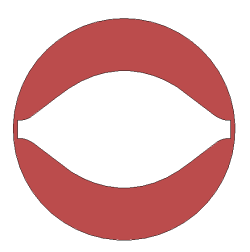
Diagram of a screw element (end view):
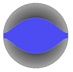
The blue in the image above indicates the cross-section of the
metal at the end of the screw. This is the area of the
cross-section in the barrel that is not extrudate. The
barrel is a slightly larger diameter than the screw, so if we show
a cross-section of the extruder with both the extrudate (red) and
the metal of the screw (blue), the full cross-section of the
barrel can be visualized:
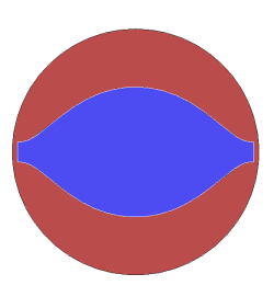
If the cross-section of the metal is removed, we are left with
just the cross-section of the extrudate:
The portion of the cross-sectional area of the barrel contains the screw element, not extrudate. This can be calculated:
The cross-sectional area of the barrel can be calculated:
The constant C3 was created to make the equation show a little
more clearly for later calculations.
So now we have the volume of extrudate carried forward per revolution of the screw by multiplying the cross-sectional area of the extrudate by the length the extruate is conveyed forward:
This tells us that the volume conveyed forward in an extruder screw is proportional to the diameter of the screw cubed. A similar calculation can be done to show the same relationship applies for twin-screw extruders. Since the residence time is proportional to diameter of the extruder for geometrically similar extruders, residence time is independent of extruder diameter for geometrically similar extruders being fed scaled feed rates and at equal screw speeds.
Heat generation in extruders occur
through viscous dissipation of energy being delivered through the
extruder screw(s). Energy input is a function of shear rate of the
extrudate. It can be shown that for geometrically similar
extruders fed at scaled feed rate, the energy input is a function
of shear rate and time in the extruder. The shear rates can be
calculated for any point in the extrudate. For the sake of an easy
geometry, a cross-section of the screw (in blue) and the extrudate
(in red) will be used for the example. This is shown in the
image below. The diameter of the barrel is D+2δ where δ is
the gap between the screw element and the barrel wall at the
narrowest point. For different areas in the extrudate, the
distance between the moving screw element and the barrrel
wall will be different.
For this example, we use the area of highest shear for the calculation, but the shear at any point could be used. The gap between the screw tip and the wall is the point of highest shear and can be expressed mathematically as: